TL494 Overview
Representative TL494 image (package may vary by manufacturer)
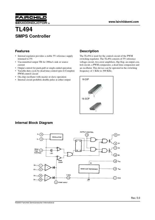
Description
The TL494 is used for the control circuit of the PWM switching regulator. The TL494 consists of 5V reference voltage circuit, two error amplifiers, flip flop, an output control circuit, a PWM comparator, a dead time comparator and an oscillator.
Key Features
- Internal regulator provides a stable 5V reference supply trimmed to 5%
- Uncommitted output TR for 200mA sink or source current
- Output control for push-pull or single-ended operation
- Variable duty cycle by dead time control (pin
- Complete PWM control circuit
- On-chip oscillator with master or slave operation
- Internal circuit prohibits double pulse at either output